Flow lines are curves that represent the paths followed by water particles as they flow through the porous medium. These lines are always perpendicular to the equipotential lines and never intersect each other. The density of flow lines indicates the velocity of the groundwater flow, with closer spacing indicating higher velocities. The purpose of a flow net is to visualize and analyze the flow patterns and characteristics of groundwater.
1 What is Graphical Construction of a Flow Net?
Figure Box 4-6 – Some flow nets may include partial flow tubes as shown here by the narrow flow tube at the bottom of the flow net. Figure Box 4-1 – Step 1 – Draw the system to scale, Step 2 – Draw equipotential lines to coincide with head boundaries, Step 3 – Draw flow lines to coincide with no-flow boundaries. Imagine a groundwater system where you wish to assess potential water table changes.
Step 4: Analyzing the Flow Net
An exception to these requirements may occur near the edge of the domain where a partial (or fractional) flow tube may be drawn. A flow net is drawn in the transformed section (Figure Box 5-6) according to the steps of flow net construction under isotropic conditions as described in section 2.2 of this book. We know the hydraulic head at the ground surface is equal to the elevation of the ponded water (0.8 m).

Rate of Seepage loss (Q)
The number of flow lines depends on the complexity of the flow system and the level of detail required. Generally, more flow lines provide a more accurate representation of the flow pattern. After completing the flow net, it is crucial to analyze it to gain insights into the flow patterns and draw flow nets potential problems. This analysis involves identifying areas of convergence and divergence, determining the flow rate and velocity, and assessing the overall flow pattern. By analyzing the flow net, engineers and geologists can make informed decisions and recommendations for various projects.
Determining the Number and Spacing of Flow Lines
Figure 4 – A plan view of flow in a confined aquifer penetrated by a deep lake and pond and laterally constrained by bedrock. The lake water elevation is 300 meters and the elevation of the pond surface is 200 meters. Flow lines diverge on the upgradient side of the bedrock island in the middle of the aquifer and converge on the down gradient side.
1 Flow Nets by Graphical Construction
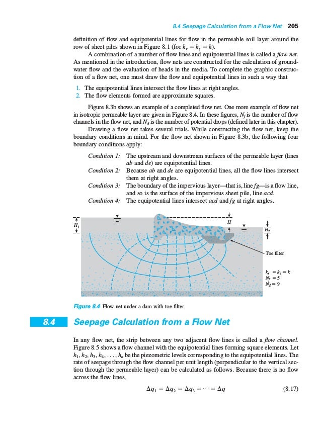
As in the paper analog, a potential difference is set up across the constant-head boundaries of the model. A sensing probe is used to determine the voltage at each of the nodal points in the network, and these values, when recorded and contoured create the equipotential net. Figure 3 – A cross-sectional view of a groundwater flow net under a dam from an upper reservoir to a lower reservoir. A flow net is comprised of two sets of lines that honor Darcy’s Law and conserve mass.
This intersection of theoretical analysis and empirical data offers a robust foundation for future research and engineering innovation. A flow net drawn over this area can help illustrate how water moves from the upstream to the downstream side, identifying zones of potential seepage that need attention in design or remediation efforts. Although manual drawing of flow nets is valuable for understanding, software can automate complex scenarios for precise analysis. Imagine a scenario where a pipe runs underground in a saturated soil environment.
- They provide a visual representation of the flow of fluids through porous media, such as soil or rock.
- StudySmarter’s content is not only expert-verified but also regularly updated to ensure accuracy and relevance.
- Flow lines are curves that represent the paths followed by water particles as they flow through the porous medium.
- Figure 5.6 is a qualitatively sketched flow net for the dam seepage problem first introduced in Figure 5.3, but with a foundation rock that is now layered.
- The highest rate of seepage into the sand will be immediately up gradient of the dam with seepage decreasing with distance up gradient.
Graphical construction of a flow net solves the two-dimensional, steady-state groundwater equation in a homogeneous and isotropic material with defined boundary conditions. Boundary conditions are discussed in another Groundwater Project book (Woessner and Poeter, 2020). Two types of boundary conditions are used in graphical construction of two-dimensional, steady-state flow nets. The flow system domain is bounded by either a constant hydraulic head boundary or a no-flow boundary. It is important to remember that “no-flow” refers to no flow across the boundary, groundwater flow occurs parallel to the boundary, such that the boundary is a flow line.
It seems to us that the transformation techniques introduced in this section provide an indirect but satisfying explanation of this phenomenon. When groundwater flowlines cross a geologic boundary between two formations with different values of hydraulic conductivity, they refract, much as light does when it passes from one medium to another. However, in contradistinction to Snell’s law, which is a sine law, groundwater refraction obeys a tangent law.
Additionally, it’s important to ensure that the equipotential lines are continuous and do not intersect or overlap with each other. If two equipotential lines intersect, it indicates a point of equal potential along that line. Overlapping lines can lead to confusion and inaccuracies in the analysis of the flow system. Once we have determined the number and spacing of flow lines, we can start drawing them.